
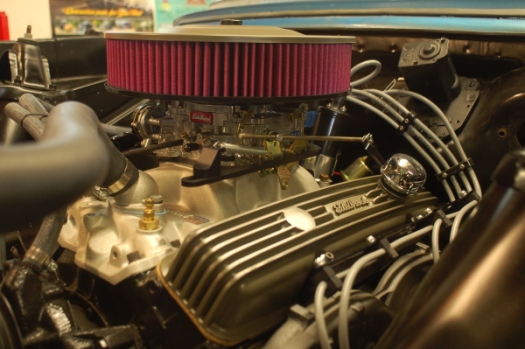
I figured it was time for a “Part 2”, if for no other reason than to convince myself I’m actually making progress on this thing! And I guess I am, when you consider that the basics of the engine swap are done and I’m now digging into the time-consuming, menial (!?) things that will put me behind the wheel and back on the road. To recap, you can read the first segment of the story here. And here’s where we are now:
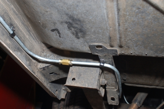
Most everything between the fenders that’s needed is there, with the exception of the battery and (ugh!!) the primary wiring. And we’ll get to that. First though, I have to connect the newly-installed fuel tank to the power plant. I need fuel lines. There are several sources for factory-replacement fuel lines. But in my case, living here in flyover country, oversize shipping is a killer for a cheapskate like me. And, there are things about my car that aren’t original. So I darkened the doorway of my favorite local NAPA store. They’re a great bunch of guys who really know what they’re doing and aren’t afraid to help out a keeper of old iron. I walked out the door with 3/8 steel brake lines, brass inverted flare unions and a bunch of line clamps. A few nights later, off and on, I had the job done. In the first picture, you can see the old fuel line that roughly follows the driveshaft tunnel. That will be removed. You can also see that the inverted flare has been cut off the tank end of the line, the nut removed, and a “bubble” flare (the first half of the inverted double-flare process) has been done to help hold the fuel hose in place after it’s clamped.

The new dual exhaust system would be a little too close to the old fuel line for my liking, so I roughly followed the routing that was used for later V-8 Chevy II models with duals. The line follows the passenger side rear subrail, around the front spring hanger, and along the passenger side inner rocker. The first line was 60″ long which placed the flare union perfectly.
The second 60″ line then followed the inner rocker and made a jog up and in toward the front subframe rails to a second flare union. Line clamps placed about 12″-15″ apart, mounted by drilling 1/8″ holes and using hex-head, self-tapping screws.

The last section was the 51″ piece, which followed the front subframe rail up to the factory-placed V-8 fuel line hole in the inner splash apron. On this line, the first line clamp was mounted to the lower edge of the subframe rail, with a 3/16″ machine screw holding it horizontally as shown. That should keep the line from rubbing the flange as it goes around the point where the subframe bolts to the body shell.

Then I cut two lengths of the appropriate hose (hose #H350A, bio-fuel compatible) and clamped it in place, one on the tank end and the other to the fuel pump. Done.
Next project: connecting the original column shift gear selector to the new 350 Turbo. Originally, the Powerglide linkage worked through a subframe-mounted bellcrank assembly which then connected a second linkage rod to the trans. Eyeballing things, and in a quest for simplicity, I figured the bellcrank assembly could probably be bypassed. So I tried Lokar’s universal column shift linkage, and again the eyeball engineering seemed to indicate it would fit just fine. If you have headers or non-stock exhaust system or steering, however, you’ll need to double check this. After arranging all the pieces on the workbench, I read through the instructions and started mocking things up. The top side, connecting to the shift selector arm on the original Chevy II steering column was pretty straightforward.
 On the bottom side, I mounted the adjustable transmission selector arm at the suggested 8 o’clock position in relation to the trans pan rail. (You can see the pan rail just to the right of the arm.)
  In my case after test-running everything that position worked just fine, but the splines on the nut insert and arm allow you to re-clock the arm as needed. You’ll also need to cut and bend the kit-supplied rod Here’s how I wound up bending mine and mounting the ends. The steering column end is on the bottom:

After test-fitting everything, before I removed it to permanently install the transmission end I put registration marks on both pieces so I’d be sure to get everything lined up correctly.

You’ll do final adjustments by moving the threaded rod ends in or out to get the transmission detents to match the selector on the column. Once that’s done, tighten the jam nuts on each end. Here’s the assembled linkage on the transmission end:

And, here’s a view looking up at the steering column connection from below, showing the clearance around the linkage.

A couple of nice things about this setup: The spherical rod ends allow leeway in alignment, and the ball inserts are nearly friction-free. Shifter action is new-car smooth. I’ve built my own column shift linkage on cars before, and actually contemplated doing it on this one too. But these days, in my neighborhood at least, foraging for small parts, linkage pieces, bushings etc. in salvage yards is not as handy as it once was. So I chose the easier method and it worked for me.
Next step: “Spaghetti”!! (the daunting task of wiring!!) That will be, I hope, somewhat easier with a Classic Update series wire harness from American Autowire. Again, with help from friends I’ve wired several cars from scratch in the past. This is the first time I’ve used a commercial wiring harness. I’m not into it very far at this point, but I think I made the right decision. Follow along as I string ’em!

Feel free to check in anytime, there’s a lot more multi-colored fun to come! And to read the next segment in this saga, click here!
Safe travels.
